Wednesday, 21 November 2012

Working principle of arc welding

The welding process which use the intense heat of an electric arc to effect a weld is known as arc welding process .
All of the arc welding process employ the same basic circuit .It is basically a fusion welding process .Contact is first  made between the electrodes and the work to create an electric circuit and then by separating the conductors an arc is formed .The arc is sustained electrical discharge .Through a path of ionized particles called plasma .The electrical energy is converted into intense heat in the arc which attains a temperature ranging from 3000 Celisse to 4500 Celisse .The heat forms a pool a of molten metal by melting the electrode end and edges of the parents metal near the arc.This pool of molten metal on solidification becomes the weld .No pressure is generally required to effect a weld .

Pit Furnace working and construction with diagram

Pit Furnace
A furnace made in pit for melting metal for taking casting process is called a pit furnace.
        It consists of a cylindrical steel shell ,closed at the bottom with a grate and covered with a removable lid.The shell is lined with refractory bricks from inside .Sometimes the furnace is completely made in brick work instead of a steel shall .The draft of the air through the furnace may be a natural draft for low melting temperature metals but a force draft with the help of ablower to accelerate the melting process in case of higher melting temperature metals and alloys.
To prepare the furnace for melting, a deep bed pf coke is kindled and allowed to burn until a state of good combustion is attained .Some of the coke is removed to make place for the crucible .The crucible is then lowered into furnace .The coke is replaced and additional coke is put to surround the crucible on all sides.Metal is then charged in the crucible and the furnace lid is replaced to give natural draft .When the metal melts and reaches the desired temperature .The crucible is removed from the furnace with special long handle tongs. De -gas and de-oxidise the metal when necessary.

Cupola Furnace working or construction

Construction and working of Cupola Furnace 
It is the constructed in the form of a hollow cylindrical vertical steel shell.It is lined from inside with a refractory material .It is generally supported on four cast iron lags mounted on a concrete base .The bottom of the furnace is closed by two cast iron doors hinged to the bed plate of the furnace .A wind box cast iron encircles to the outside of the furnace bottom .This box is connected to the furnace blower by pipe known as the blast pipe .Air which supplies the oxygen necessary to burn the fuel ,is forced through the cupola by a blower .The top of the furnace is shielded by a mesh screen and topped with a cone shaped spark arrester ,which permits the free vent of the waste gas and deflects spark and dust back into furnace.
working 
First of all ,the waste material dumped on the floor under the furnace after the previous heat must be cleared away.the cupola repair man then enters the cooled furnace and cleans out the slag and refuse on the lining and around the tuyeres from the previous run.Any bad spots or broken bricks are repaired with a refractory material to return the lining to its original shape .Then the bottom doors are swung into the position and the prop placed under them .all cracks are closed with fire clay and a layer of black moulding sand is placed on bottom .This sand is rammed down and given a slope towards the spout .The kindling material usually soft,dry pieces of wood is placed on the sand bed and a charge of coke is put in the furnace .The kinding and bed charge of coke are ignited through the tap-hole opening .As soon as the coke bed is thoroughly ignited ,the first charge of metal ,pig iron ,scrap and flux is placed on top of the bed charge of glowing coke .A weighed charge of coke is placed on top of the metal charge .After the cupola is fully charged upto the charging door ,the iron should soak in the heat for 45 mins or longer .No forced draft is used during this period .The only draft comes from tuyere peep hole and spout openings. As the charge descends in the furnace it is preheated untill it reaches the area where the melting takes place .The metal melts in small drops .Intermittently ,the tap hole is oppened ,allowing the metal to flow through the spout into the receving ladder.It is then closed again with a conical clay plug.This procedure is repeated ,until all the metal is melted and poured.

Tuesday, 20 November 2012

Seam welding (schematic Arrangement)

SEAM WELDING
This type of resistance welding which consists in making a continuous seam of weld on two overlapping metal sheets is known as seam welding .illustrates arrangement of a seam welding .
Seam Welding ( Schematic Arrangement)

This process of welding consists in making a continuous weld on two overlapping metal sheets .Heat obtained from the resistance of the current produces the necessary fusion and joint .The current is passed through the overlapping sheets which are held togther under pressure between two circular electrode .timed pluses of currents pass through the metal as it workpieces between the electrodes to form overlapping elliptical wleds .the timing of the welds and the movement of the work cooling must be adjusted so the workpieces do not too hot. External cooling of the work is used to avoid overheating.

Spot welding process with diagrams


SPOT WELDING 
That type of resistance welding process which produces only one weld pot a time between two metal sheets, is known as spot welding.
Process Illustrates the schematic arrangement of spot welding .
It is probably the simplest type of resistance welding .two or more metal sheets are held between electrodes .the welding cycle begins with the electrodes holding the metal sheet under pressure before passing the current ,and for a period known as the squeeze time .A current of sufficient amperage and low voltage is then passed .this causes the metal in contact with the electrodes to immediately rise to a welding temperature .soon after reaching this temperature ,the pressure between the electrode squeeze the metal together completes the weld.

Resistance Welding and its types

RESISTANCE WELDING 
The process of welding metal pieces by passing heavy current through them which results in a local heating of these pieces ,and then completing the weld by the application of pressure.is known as resistance welding .
Principle : It is based on the well known principle that heat is generated by the resistance offered to the flow of electrical current. since the interface the two joining surfaces is the point of greatest resistance ,it is also the point where greatest heat is generated . In simple resistance welding a high -amperage low voltage current is passed from one adjoining workpiece to the other until becomes heated to a temperature that is high enough to cause localised fusion and the formation to sequeeze the two parts into a localized homogeneous mass.
 TYPES OF RESISTANCE WELDING
The principle types of resistance welding may be enumerated as below
1.spot welding 2. Projection welding 3.Seam Welding  4.Butt welding  5. flash welding 6. percussion welding

METAL INERT GAS ARC WELDING (MIG WELDING)

That type of arc welding which uses a consumbale metal electrode in an inert gas atmosphere to produce a weld ,is known as MIG metal inert gas ) welding.


Process illustrates the working principle of a MIG welding while.The schematic arrangement of MIG welding equipment .The arc is struck between the metal electrode and the workpiece .The electrode is in the form of a continuous wire which is fed into the arc ,by an adjustable speed electric motor running the wire feed rolls at the same speed at which it is melted and deposited in the weld.this process can be used for welding in positions however best results are obtained in flat and horizontal position.
fig.1 Gas -Arc (MIG) Welding Working Principle

fig 2. MIG Welding Equipment ( Schematic Arrangement )
Usually D.C. with straight polarity is used in MIG welding .AC is not used in this method .Use of D.C . reverse polarity enables a deeper penetration and  clean weld surface.Inert arogn,helium .carbon dioxide or a mixture of these gases is used for providing the inert gas shield .Formerly argon was mainly used ,but now carbon dioxide is more widely used .

Application : This process also finds an extensive use in missiles and aerospace fabrication.

Induction Welding process And Application

INDUCTION WELDING

That welding process in which weld is produced by the the heat obtained from the resistance of the weldment to flow of an an induced electrical current is known as induction welding.

process : In opreation a high current is induced with both edges of the work close to where weld is to be made .Heating to welding temperature is extremely rapid and the joint is completed by pressure rolls or contacts.A form  of induction welding known as high-frequency welding is similar except that the current is supplied to the conductor being welded by direct contact.High -frequency current flow near the surface of the metal and as heating is almost instantaneous,there as chance of hamful oxides high frequency welding.
Application ; It is a high -speed process and is best suited for high production use. Welding speed ranges from 60 m/mt to 300 m/mt. It is now,being used for most metals ,e.g,copper and copper alloys,nickel ,zirconium and many types of steels.

CORE PRINT

The projections placed on pattern to form seats in the mould for introducing dry sand cores in the mould ,are known as core -prints.
Core Print
core -prints make impressions in the form seats into which the cores may be set and thus reattained in proper position in the mould .when the reversal of a core in the mould would spoil the casting ,the prints are made of such a size and shape that would be impossible to set the core in any position except the proper one.
Core prints should be made to give the least inconvenience in moulding .the print of the core should exactly fit the core seat.the print should be of sufficient and will size and so that impression in the sand will have plenty of bearing surface and will not be crushed out of shape by the weight of the core or by the molten metal.

Ultrasonic welding process and application

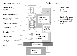
The process of joining metal pieces by the localized application of very high frequency .i.e. ultrasonic frequency ,to the metal pieces held together under pressure is known as ultrasonic welding.


process;  ultrasonic welding combines pressure and high frequency motion to form a solid- state bond .a transducer which changes the high frequency electrical power into vibratory energy.The ultrasonic used is coupled to a force sensitive system that contains a welding tip on one end. Either stationary tips,for spot welds, or rotating discs for seam weld can be used.

Application : this processs can be used only for the materials upto about 3 mm in thickness ,alought equipment is being developed to extend this range .there is no minimum limit to the sheet thickness that can be welded .ultrasonic welding is excellent for joining thin sheets to ultrasonic welding is particularly adaptable for joining electrical and electronic components ,also in aircraft and missiles .

Pattern differs from a finished casting


MOULDING PATTERN

A model of anything  so constructed that it may be used for forming a mould or impression in damp sand or other suitable material is known as a pattern .The mould produced with the help of a pattern ,when filled with molten metal or substances that solidify ,forms a reproduction of the pattern and is known as a casting .pattern differs in a number of respects from the resulting casting these differences known a pattern allowances ,compensate for metal shrinkage ,provide sufficient metal for machined surface ,and facilitate moulding .A through understanding of these allowances is necessary for successful pattern design and construction .

Cantrolling welding defects

These are the welds with voids ,blow holes or pockets which weaken welds appreciably and gas acts as stress risers from which cracks spread.porosity in welding is a result of dissolved gases or gases released during the welding process ,being trapped in the metal .when there is insufficient time to espace pror to solidification